Delivery outside GER for business customers only
Quality directly from the manufacturer
Langzeitstabile Temperaturfühler über Jahre
Advice directly from experts
 

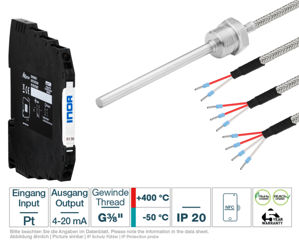
Hat rail transmitter + Screw-in probe G3/8 " glass fibre

€ 77,21 *

Prices plus VAT plus shipping costs of 4,95 € to GER (incl. VAT)

Delivery time 5 Workdays to NL, BE, AT (GER -1 workdays)
Repeated order: check settings carefully and change if necessary.
Hutschienen-Transmitter
Ihr passender Hutschienen-Transmitter
Transmitter für Pt100/Pt1000
Bitte konfigurieren Sie Ihren Einschraubfühler
A - Messelement

Bitte prüfen Sie, welches Messelement (Thermistortyp oder Pt) für Ihre Anwendung der Passende ist. Wichtige Informationen zum Messelement entnehmen Sie bitte den Kennlinien und Datenblättern. Diese finden Sie in der Langbeschreibung oder in unserem Download-Bereich.

keine Auswahl
(A011) Pt100 Klasse A
(A012) Pt100 Klasse B
(A013) Pt100 1/3 Klasse B
(A014) Pt100 1/10 Klasse B
(A031) Pt1000 Klasse A
(A032) Pt1000 Klasse B
B - Anschlussart

Bei Zwei-Leiter-Schaltungen addiert sich der Eigenwiderstand der Anschlussleitung zum Widerstandswert des Messwiderstands (Thermistor oder Pt) und verfälscht somit das Messergebnis. Ist der Widerstandswert des Messwiderstands groß gegenüber dem Eigenwiderstand der Anschlussleitung, so kann dieser Eigenwiderstand vernachlässigt werden. Bei Messwiderständen mit geringerem Widerstandswert (z.B. PT100), kann der Leitungseigenwiderstand die Messgenauigkeit jedoch signifikant verringern. Aus diesem Grund empfehlen wir die Zwei-Leiter-Technik in Verbindung mit kleinohmigen Messwiderständen nur dann, wenn Sie vergleichsweise kurze Anschlussleitungen, also kleinohmige Anschlussleitungen, verwenden können.

Für Applikationen, die eine sehr genaue Temperaturmessung erfordern, empfehlen wir Ihnen eine Drei- oder sogar Vier-Leiterschaltung zu verwenden.

Bei der Dreileiter-Schaltung wird der Leitungswiderstand jeder der drei angeschlossenen Leitungen mit Hilfe der dritten angeschlossenen Leitung ermittelt (alle Anschlussdrähte müssen exakt gleich lang sein) und anschließend vom gemessenen Gesamtwiderstand (Messwiderstand+Leitungswiderstand) abgezogen werden, so dass effektiv nur der Widerstandswert des Messwiderstands für die Temperaturbestimmung verwendet wird. Diese Subtraktion kann beispielsweise in der Messelelektronik automatisch durchgeführt werden.

Die sicherste und genaueste Messung erreichen Sie mit Hilfe einer Vierleiter-Schaltung. Hier wird auf jeder Seite des Messwiderstands eine zusätzliche Leitung angeschlossen. Zwei Leitungen dienen der Spannungsversorgung, die zwei anderen werden verwendet, um den Leitungswiderstand (ggf. auch asymmetrisch, also auch bei unterschiedlich langen Anschlussdrähtchen) zu ermitteln und vom Messwiderstandswert abzuziehen. Diese Subtraktion kann beispielsweise in der Messelelektronik automatisch durchgeführt werden.

(B2) 2-Leiter
(B3) 3-Leiter
(B4) 4-Leiter
C - Einbaulänge

Jeder Fühler benötigt eine Mindest-Eintauchtiefe, um die Temperatur des zu messenden Mediums annehmen und korrekt messen zu können. Faustformel: optimalerweise sollte die Eintauchtiefe 10-mal dem Schutzhülsendurchmesser entsprechen, mindest sollte jedoch ein 5-facher Wert verwendet werden.

(C0050) 50 mm
(C0100) 100 mm
(C0150) 150 mm
(C0200) 200 mm
(C0250) 250 mm
(C0300) 300 mm
(C0400) 400 mm
(C0500) 500 mm
E - Material Anschlussleitung

Bitte stellen Sie sicher, dass die technischen Daten der Anschlussleitung, insbesondere hinsichtlich Temperatur und IP-Schutzklasse, zu Ihrer Applikation passen. Detailierte Informationen finden Sie in unseren Datenblättern.
Temperaturbereiche unserer Leitungen:
Glasseide: -50 °C bis +400 °C

(E3300) GLS/VA (2 x 0,22 mm²)
(E3301) GLS/VA (3 x 0,22 mm²)
(E3302) GLS/VA (4 x 0,22 mm²)
F - Länge Leitung

Bei sehr langen Anschlussleitungen beachten Sie bitte den Einfluss des Eigenwiderstandswerts der Leitung auf die Messgenauigkeit. Für Fühler mit Pt-oder Ni-Messelementen empfehlen wir in diesem Fall den Einsatz einer Drei- oder Vierleiterschaltung.

(F010) 1 m
(F020) 2 m
(F030) 3 m
(F040) 4 m
(F050) 5 m
(F100) 10 m
(F150) 15 m
(F200) 20 m
(F010) 1 m
(F020) 2 m
(F030) 3 m
(F040) 4 m
(F050) 5 m
(F100) 10 m
(F150) 15 m
(F200) 20 m
(F010) 1 m
(F020) 2 m
(F030) 3 m
(F040) 4 m
(F050) 5 m
(F100) 10 m
(F150) 15 m
(F200) 20 m
G - Stecker
(G01) isolierte Aderendhülsen
H - Knickschutz

Der Knickschutz schützt die Anschlussleitung des Fühlers am Übergang zur Fühlerhülse vor mechanischen Belastungen (wie sie z.B. bei kleinen Biegeradien auftreten).

(H0) Ohne (Standard)
(H1) Metall-Knickschutzfeder
Image Changer
Wie viele Transmitter und Fühler benötigen Sie?
Price calculation
Basic price
€ 77,21
Ihr passender Hutschienen-Transmitter:  
A - Messelement:  
B - Anschlussart:  
C - Einbaulänge:  
E - Material Anschlussleitung:  
F - Länge Leitung:  
G - Stecker:  
H - Knickschutz:  
Menge:  
Configuration is incomplete - please check it!
  • 803180-3091
Our Payments
MasterCardPayPalInvoiceVISAPrepayment

Advantages

Questions about the article?
Our employee will be happy to help you:
Julian Mäntele
Tel.: +49 (0)7653 96 59 771
E-Mail: jmaentele@testo-sensor.de
Active Screw-in probes with Pt resistance sensors are equipped with a temperature transmitter in...more
Product information "Hat rail transmitter + Screw-in probe G3/8 " glass fibre"

Active Screw-in probes with Pt resistance sensors are equipped with a temperature transmitter in DIN rail form. They convert the change in resistance into a standardized signal (mA). This means that the temperature measurement signals can always be transmitted safely, easily and even over longer distances to your control or display. Screw-in probes with glass fibre cables are shielded and measure the temperature in pipelines or vessels up to +400 °C. They are crimped and also have a poorer seal than other cables due to the insulation material used.

Directly to the downloads

________________________________

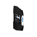
The APAQ R130 for Pt100 and Pt1000 sensors is a DIN rail transmitter for installation on standard DIN rails according to DIN EN50022. The sophisticated product design leaves enough space for mounting. It is optimally designed for use in plant and machine construction and is characterized by high accuracy, reliability, long-term stability and its robust product design. The transmitter is extremely insensitive to external influences such as vibration and EMC interference. Installation and commissioning are particularly user-friendly. For example, parameterization can be carried out wirelessly, conveniently and easily via the cell phone app using NFC technology. The monitoring functions such as sensor break monitoring, sensor short-circuit and measuring range monitoring can also be activated via this.

Here you can find our downloads for Hat rail transmitter for Pt100/Pt1000 APAQ-R130

pdf-download Data sheet Hat rail transmitter for Pt100/Pt1000 APAQ-R130
pdf-download Instruction manual Hat rail transmitter for Pt100/Pt1000 APAQ-R130
pdf-download Declaration of Conformity Hat rail transmitter for Pt100/Pt1000 APAQ-R130
 

Hat rail transmitter - Special features

Inputs and outputs Input: Pt100, Pt1000 as 2-, 3- and 4-wire
Output: 4 to 20 mA, temperature linear
Accuracy & Long-term stability Accuracy: Max. ±0,15K or ±0,15% of span
Long-term stability: max Drift of ±0.05°C or ±0.05% pf span / year
Design Robust - vibration and shock resistant design
Suitable for hat rails according to DIN EN50022
Compact housing design
Facilitated mounting
Parametrization Configuration - wireless via NFC technology
Free App for Iphone, Android & Huawei
Parameterization templates for fast mass configuration
Simple configuration with "copy and paste" in no time at all
Alarm function configurable via app
Sensor break monitoring
Sensor short circuit
Measuring range monitoring
 

Hat rail transmitter - Measuring element

Measuring element Norm Maximum configurable measuring range Min. Span Accuracy
Pt100 IEC 60751 | a=0,00385 -200 °C to +850 °C | -328 °F to +1562 °F 20 °C | 36 °F ±0,15 °C| ±0,15 % 1}
Pt1000 IEC 60751 | a=0,00385 -200 °C to +850 °C | -328 °F to +1562 °F 20 °C | 36 °F ±0,15 °C| ±0,15 % 1}
Temperature influence of 20 °C / 68 °F | Max. of ±0.015°C / °C or ±0.015 % of span / °C | Max. of ±0.015°F / °F or ±0.008 % of span / °F | 1} of span
Connectinon type 2-, 3- and 4-Wire
Sensor current ≤ 0,5 mA
Resistivity 50 Ω / Wire
 

Hat rail transmitter - General information about the input

Zero adjustment Within measuring range
 

Hat rail transmitter - Output

Output type analog, temperature linear for RTD
Output signal (mA) 4 to 20
Parametrization / Scaling Configurable via NFC
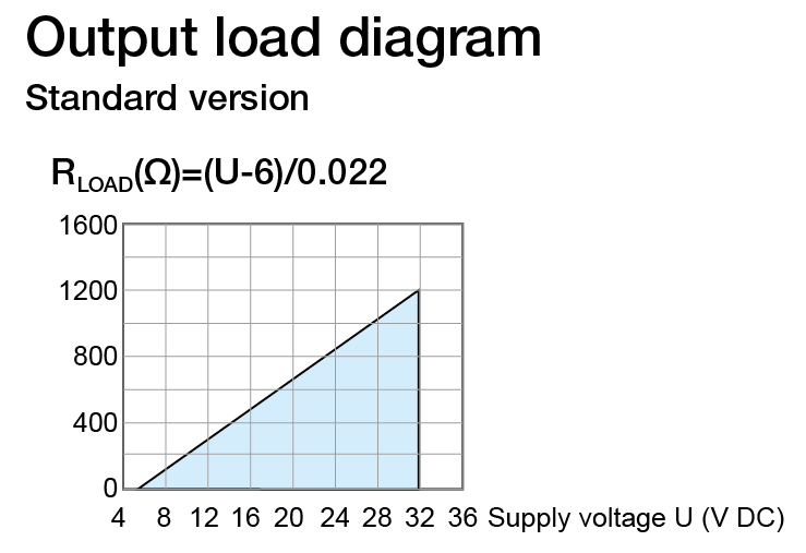
Load 818 Ω at 24 VDC
Connection type 2-wire
 

Hat rail transmitter - Time response

Closing time / Update time (Inor) ~150 - 300
Heating period The specified accuracy is reached after max. 4 minutes
Signal attenuation / Ajustable output filtering (Inor) 0,4 to 26 adjustable via App
Measuring cycle < 1
 

Hat rail transmitter - Sensor monitoring & sensor error

Sensor break / Short circuit Upscale (≥21.0 mA) or Downscale (≤3.6 mA)
Sensor failure effects (Inor) according to NAMUR NE43
 

Hat rail transmitter - Accuracy and stability

Temperature influence
TC Type B, E, J, K, R, S, T see table below
TC Type N (-100...+1300 °C) ±0,01 % < 4000 Ω 2} < ±0,02 % of span per °C
TC Type N (-270...-100 °C) ±0,01 % of span per °C
Influence of the sensor cable
Thermocouples and Voltage Negligible
Further data
Supply voltage influence <±0.005 % of span per volt
Long-term drift ±0.05 % of span per year
 

Hat rail transmitter - Type

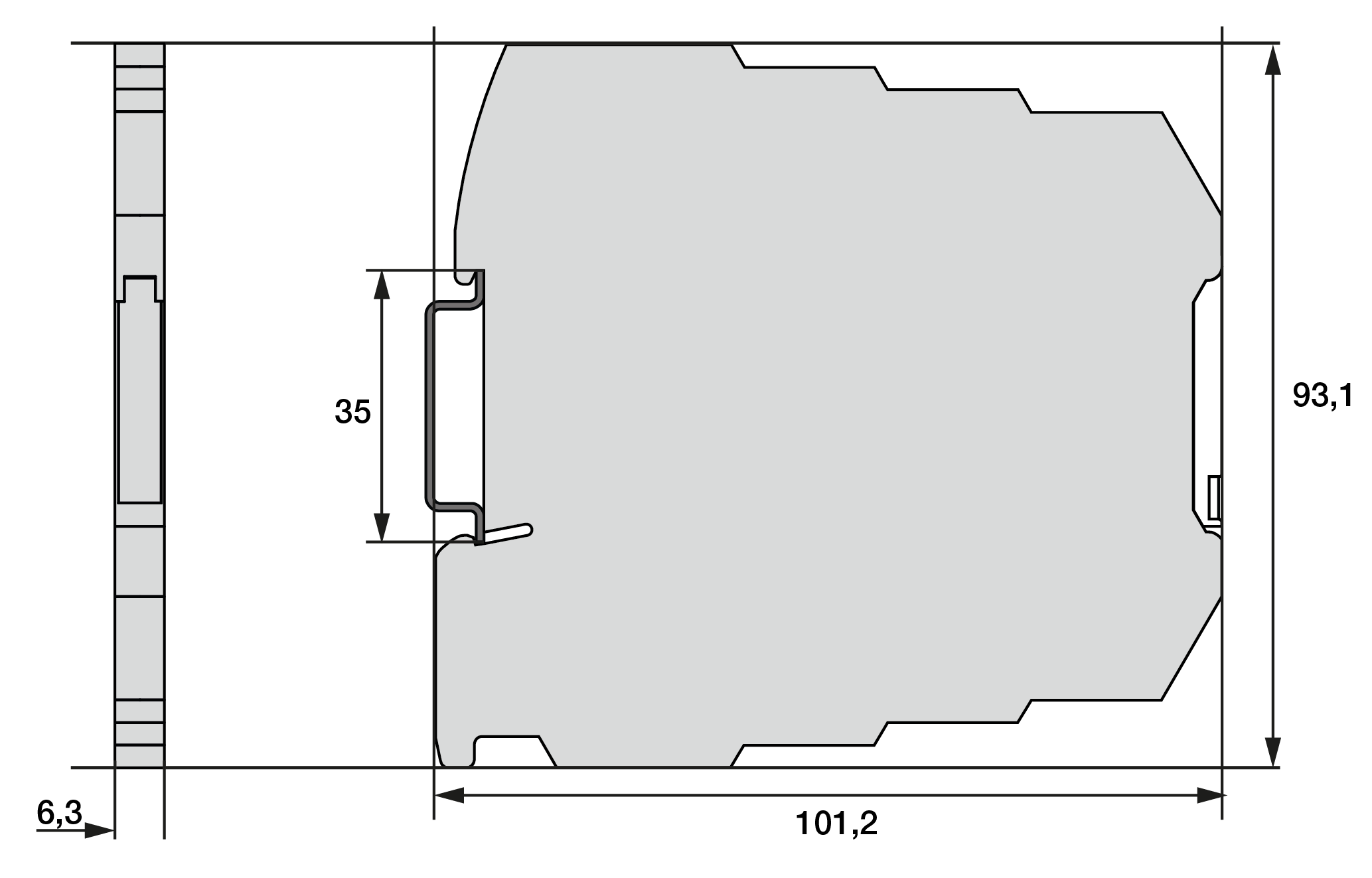
Dimensions See drawing
Material | Flammability V0/HB, RoHS compliant
Mounting 35 mm hat rail according to DIN 50022 / EN 60715
Connection Single wires, max. 1,5 mm², AWG 16
Weight 40 All dimensions in mm
 

Hat rail transmitter - General data

Isolation none
Supply Voltage (VDC) 8 to 32, polarity protected
 

Hat rail transmitter - Ambient conditions

Ambient Temperatur Storage: -40 °C to +85 °C | -40 °F to +185 °F
Operating: -40 °C to +85 °C | -40 °F to +185 °F
Humidity 0 to 98 (non-condensing)
Protection Housing IP20 | Anschlussklemmen IP00
Vibration according to IEC 60068-2-6, Test Fc, 10bis2000 Hz, 10 g
Shock according to IEC-60068-2-27, test Ea
Environmental influences according to IEC 60068-2-31:2008, Test Ec
 

Hat rail transmitter - EMC

Standard Directive: 2014/30/EU | Harmonized standards: EN 61326-1, EN 61326-2-3
Immunity performance ESD, radiated EMC fields, magnetic fields: Criterion A
Burst, conducted RF: Criteria A
Overvoltage: standard deviation 1% of span
 

Hat rail transmitter - Factory configuration (if not ordered otherwise)

Input Pt100, 3-wire, 0 °C to 100 °C
Output (mA) 4 to 20
Sensor control Upscale (≥21.0 mA)
 

Hat rail transmitter - Mounting

You can easily mount the APAQ R130 hat rail transmitter on 35mm hat rails according to DIN EN50022. The mounting is easy because you can fix the transmitter on the rail without any tools.
Mounting material for the installation of the transmitter is available as accessory.
Important: To prevent measuring errors, the connecting screws for fastening the connecting cable must be tightened firmly.
Mounting and dismounting of the transmitter
(1) Fix the upper part of the transmitter on the rail
(2) Then press the lower part of the transmitter onto the rail. The electrical connection is made according to the wiring diagram
(4) To remove the transmitter, use a screwdriver and bend the latch downwards
 

Hat rail transmitter - Configuration | Parametrization


Before making a configuration of APAQ C130TC you need to do following:
Make sure that you have a mobile device with NFC communication activated.
Download the app INOR Connect to your mobile device.
Required versions:
iOS: iOS 13 or later and Iphone 7 or later
Android: Android 4.4 or later
Configuration procedure:
Launch the app by clicking on the App icon or holding your mobile device against the transmitter on the part of the device where NFC is located (only possible with Android). Click on “Read Configuration” and hold your mobile device against the transmitter as explained in the first section.
In the app you can edit the following:
Sensor type and number of wire circuits
Measuring range
Upscale or Downscale
sensor control
TAG-number
Password settings
In the configuration window you can enter and change the parameters. The selected configuration is transferred to the transmitter by clicking the "Send to transmitter" button. After the transfer is completed, the transmitter uses the new parameters.

________________________________

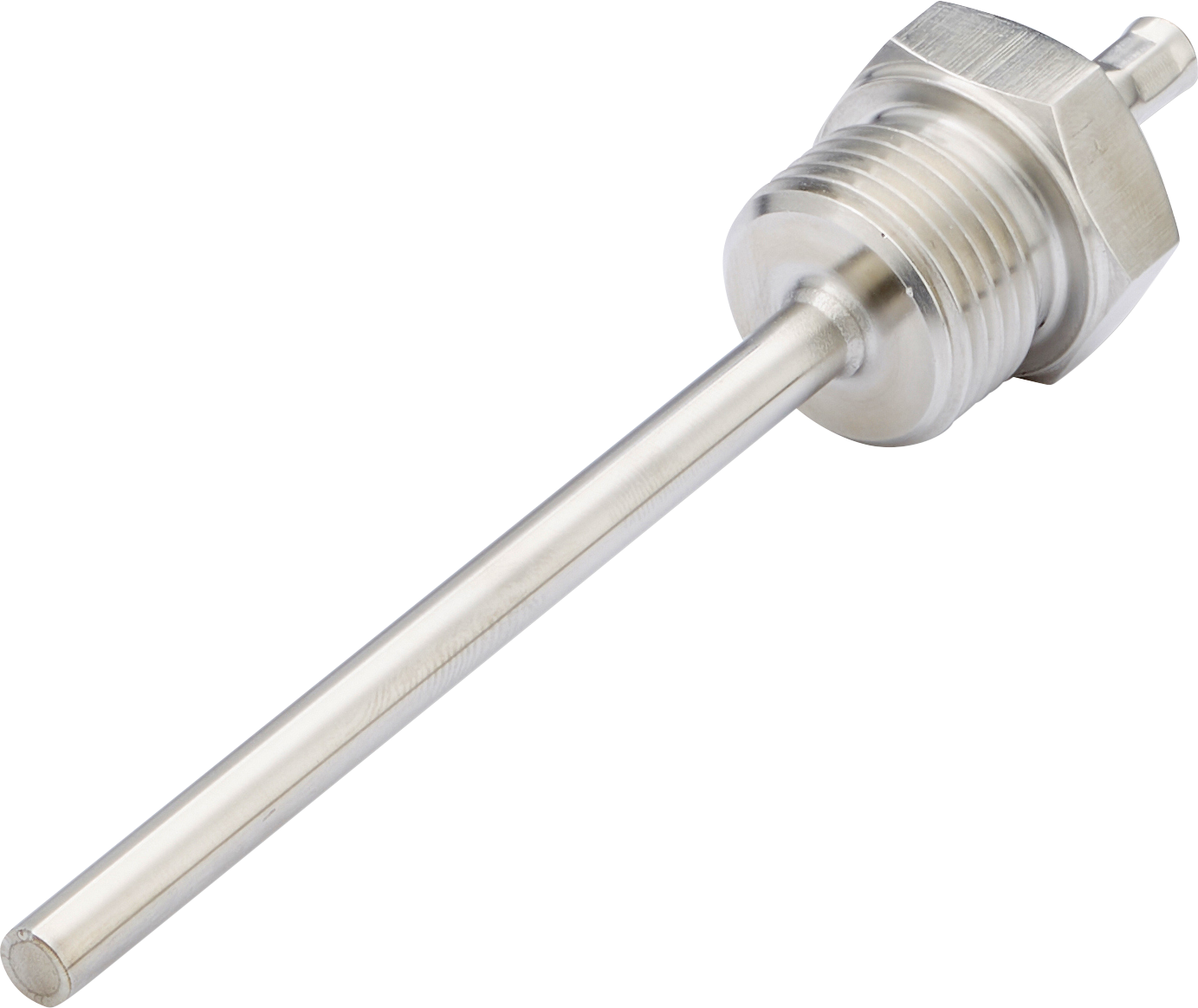
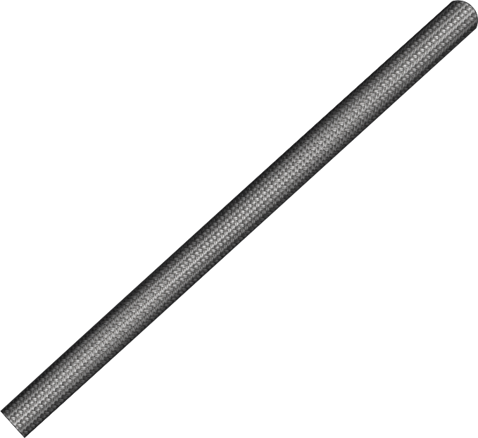
Screw-in probes with glass fibre cables are shielded and measure the temperature in pipelines or vessels up to +400 °C. They are crimped and also have a poorer seal than other cables due to the insulation material used.

Here you can find our downloads for the Screw-in probe G3/8 " with glass fibre cable

pdf-download Data sheet Screw-in probe G3/8 " with glass fibre cable
pdf-download Instruction manual Screw-in probe G3/8 " with glass fibre cable
pdf-download Operating instruction Screw-in probe G3/8 " with glass fibre cable
pdf-download Declaration of Conformity Screw-in probe G3/8 " with glass fibre cable
 

Screw-in probe - General Information

Measuring range -50 °C to +400 °C depending on sensor type and connection cable
Perm. °C range cable -50 °C to +400 °C
Accuracy depending on sensor type
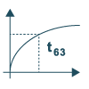
Response time t63 / t99: information is available on request
Pull-out force ≥ 30 N
                                       

Screw-in probe - Supply and output

Max. measurement current max. 1 mA
Supply voltage approx. 5 V depending on measurement current
Measurement signal passive (resistance value)
 

Screw-in probe - Ambient conditions

Protection class IP20 according DIN 60529 (depending on cable)
Humidity and moisture condensation resistance according to application-specific qualification
 

Screw-in probe - Certificates and Standards

Standards DIN EN 61326-1:2013 | DIN EN IEC 63000:2019-05
Directive RoHS 2011/65/EU | 2014/30/EU
Certificates Certificate of suitability (on request)
 

Screw-in probe - Technical Drawing

A - Measuring element
B - Connection type
C - Mounting length
E - Material connection cable
F - Length connection cable
H - Bend protection
G - Connector
All dimensions in mm
 

Screw-in probe - Measuring element

Measuring element Perm. range °C Accuracy / Tolerance resistance
Pt100 -50 °C to +400 °C Class B dT = ±(0,30 °C + 0,005|t|)1}
Pt100 -50 °C to +300 °C Class A dT = ±(0,15 °C + 0,002|t|)1}
Pt100 -50 °C to +200 °C 1/3 Class B dT = ±(1/3 · (0,30 °C + 0,005|t|))1}
Pt100 ±0 °C to +100 °C 1/10 Class B dT = ±(1/10 · (0,30 °C + 0,005|t|))1}
Pt1000 -50 °C to +400 °C Class B dT = ±(0,30 °C + 0,005|t|)1}
Pt1000 -50 °C to +300 °C Class A dT = ±(0,15 °C + 0,002|t|)1}
1} according to IEC 751 / EN 60751 | The measuring range depends on the measuring element and the connecting cable.
 

Screw-in probe - Possible connections

Measuring element 2W 3W 4W
Pt Checkmark Checkmark Checkmark
 

Screw-in probe - Screw-in thread

Thread
Material thread Stainless steel 1.4301 | SUS 304
Length (mm) 12
Thread G3/8 "
Wrench size 24
Protection sleeve
Material Stainless steel 1.4571 | 316TI
Diameter (mm)1} 6
Mounting length (mm)2} 50, 100, 150, 200, 250, 300, 400, 500
1} Tolerance ± 0,1 mm | 2} Tolerance ± 1%
 

Screw-in probe - Material connection cable

Color: steel, Perm. range °C: -50 to +400
Material (Outside / Inside) Ø Outside (mm) Cross section (mm²)2} Color strand Ω / m1}
Varnish 3,2 ± 0,2 2 x 0,22 rd, wt 0,09
Varnish 3,2 ± 0,2 3 x 0,22 rd, wt, rd 0,09
Varnish 3,4 ± 0,2 4 x 0,22 rd, wt, rd, wt 0,09
Length (m) 1, 2, 3, 4, 5, 10, 15, 20
Insulation resistance: ≥ 100 MOhm at min. 100 VDC | Cable available as accessory | 1} per single strand | 2} Tolerance ± 0,03 mm²
 

Screw-in probe - Connector

Insulated end ferrules (50 mm)
 

Screw-in probe - Bend protection

Version Without (Standard), Metal bend protection
Length (mm) 50
Material Stainless steel spring 1.4310 | SUS 302
 

Screw-in probe - Delivery

Assembly instructions via process connection
Delivery and Packaging Probe, seperatly packaged in PE bag
Matching accessories Heat-conducting paste
 

Screw-in probe - Important assembly advices

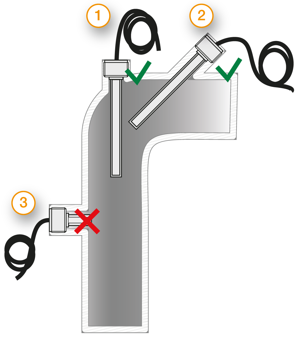
Measurement errors can occur due to heat dissipation to the environment. To keep these as small as possible, we recommend immersing the protection sleeve of your temperature probe as deeply as possible in the medium to be measured during installation. The optimum installation depth should be 10-15 times the Ø of the protection sleeve or, when using an immersion sleeve, the Ø of the immersion sleeve. When installing in pipelines whose Ø does not have a sufficiently deep installation depth, you should install the probe either at an angle or in a pipe elbow. Make sure that you have sufficient space so that the probe can be removed again. 1) Installation with sufficient installation depth 2) Installation at an angle with small pipe Ø 3) Not like this: Minimum installation depth not reached

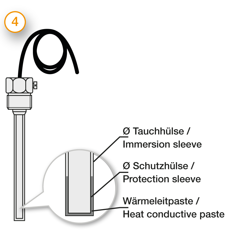
Installation by using an immersion sleeve (4): Please ensure that the Ø and length of the immersion sleeve are selected to suit the installation situation so that the minimum immersion depth can be achieved. Please also pay attention to the correct process connection. Since the probe is not inserted directly into the medium, but via the immersion sleeve, the response times are somewhat slower. The probe should be selected in such a way that the protection sleeve touches the bottom of the immersion sleeve and that the air cushion around the protection sleeve is as small as possible. The use of thermal paste can improve the response times.

Please lay the cable in such a way that no water can penetrate the probe and with reserve loop (4). This allows you to extend the probe without disconnecting the electrical connection.


Qualification measurement series to ensure the function of our temperature probes over their service life

Qualifizierungsmessreihe Robust even with temperature changes Temperature probes are exposed to harsh environmental conditions, such as changing temperatures and humidity, and should still work reliably in the field for 15 years or more. Checkmark
Qualifizierungsmessreihe Resistant to heat and humidity Extremely varying ambient conditions cause immense stress for the temperature probe and the design must be suitably robust and qualified.        
Qualifizierungsmessreihe Long-term stable in any weather Continuous exposure to sunlight, snow, fog, cold and ice shall not impair the function of the temperature probe and compliance with the specification.        
Qualifizierungsmessreihe Robust even under high vibration load Depending on the application, compressors and fans generate strong vibrations which are transmitted to components and cables. Therefore the used temperature probes have to be vibration resistant (20g). Checkmark
Qualifizierungsmessreihe Reliable in practice: high pull-out force The robust design ensures the necessary cable pull-out resistance, even under vibration and higher temperatures. Checkmark
Qualifizierungsmessreihe Efficient through short response time Depending on the application, short response times may be necessary to ensure efficient control of the system. Our sensor design is optimised for this requirement and we prove response times.        
Qualifizierungsmessreihe Corrosion-resistant even in salt spray Temperature probes are also used in coastal regions. For this reason, the temperature probes must also be able to withstand salty air for a lifespan of 15 years. Checkmark
Checkmark

Applicable for this probe type

Properties
Measuring element: Pt100 1/3 Class B, Pt100 1/10 Class B, Pt100 Class A, Pt100 Class B, Pt1000 Class A, Pt1000 Class B
industry: Air conditioning and ventilation technology, Automotive, Building automation, Food industry, Heating technology, Machinery and apparatus engineering, Pharmaceutical industry, Plastics industry, Power generation, Refrigeration, White goods
Output: 4-20 mA
Input: Pt100/ Pt 1000 resistor
Process connection: G3/8 "
Material cable: Glass fibre
Temperature range: -50 °C to +400 °C
Connection type: 2-Wire, 3-Wire, 4-Wire
Type: Hat rail transmitter
Related links to "Hat rail transmitter + Screw-in probe G3/8 " glass fibre"
Available downloads:
Read, write and discuss reviews...more
Customer evaluation for "Hat rail transmitter + Screw-in probe G3/8 " glass fibre"
Write an evaluation
Jede Verbraucherbewertung wird vor ihrer Veröffentlichung auf ihre Echtheit überprüft, sodass sichergestellt ist, dass Bewertungen nur von Verbrauchern stammen, die die bewerteten Produkte auch tatsächlich erworben/genutzt haben. Die Überprüfung geschieht durch manuelle Überprüfung in Form eines Abgleichs der Bewertung mit der Bestellhistorie des Warenwirtschaftssystems, um einen vorangegangenen Produkterwerb zur notwendigen Bedingung für die Veröffentlichung zu machen.
Please enter these characters in the following text field.
I have taken note of the Privacy Policy.

The fields marked with * are required.

Einschraubfühler G3/8 " mit Glasseide-Leitung Vorderansicht Screw-in probe G3/8 " with glass fibre cable
€ 18,31 *
Order number: 803180-3011
Add to shopping cart
Hutschienen-Transmitter für Pt100/Pt1000 APAQ-R130 Vorderansicht Hat rail transmitter for Pt100/Pt1000 APAQ-R130
€ 58,90 *
Order number: 809700-2001
Add to shopping cart
Hutschienen-Transmitter + Einschraubfühler G3/8 " PVC - Vorderansicht Hat rail transmitter + Screw-in probe G3/8 " PVC
€ 71,96 *
Order number: 803150-3091
Add to shopping cart
Hutschienen-Transmitter + Einschraubfühler G3/8 " Silikon - Vorderansicht Hat rail transmitter + Screw-in probe G3/8 "...
€ 73,01 *
Order number: 803160-3091
Add to shopping cart
Hutschienen-Transmitter + Einschraubfühler G3/8 " PFA - Vorderansicht Hat rail transmitter + Screw-in probe G3/8 " PFA
€ 76,51 *
Order number: 803170-3091
Add to shopping cart
Hutschienen-Transmitter + Einschraubfühler G1/2 " Glasseide - Vorderansicht Hat rail transmitter + Screw-in probe G1/2 "...
€ 77,72 *
Order number: 803180-1091
Add to shopping cart
Hutschienen-Transmitter + Einschraubfühler G1/2 " Glasseide - Vorderansicht Hat rail transmitter + Screw-in probe G1/4 "...
€ 77,12 *
Order number: 803180-4091
Add to shopping cart