Prices plus VAT plus shipping costs of 4,95 € to GER (incl. VAT)
Delivery time 6 Workdays to NL, BE, AT (GER -1 workdays)
| Quantity: |
- Order number: 809700-1901


Advantages
- We are ready to deliver: All information here
- Advice directly from experts
- Quality directly from the manufacturer
- Long-term stable temperature probes over years
- B2B customers welcome: All information here

Our employee will be happy to help you:
Julian Mäntele
Tel.: +49 (0)7653 96 59 771
E-Mail: jmaentele@testo-sensor.de
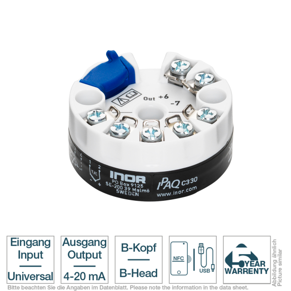
The IPAQ C330 for resistance sensors and thermocouples for installation in temperature probes with connection heads in DIN B or larger. The well thought-out product design leaves sufficient space for mounting. It is optimally designed for use in plant and machine construction and is characterized by high accuracy, reliability, long-term stability and its robust product design. The transmitter is extremely insensitive to external influences such as vibration and EMC interference. Installation and commissioning are particularly user-friendly. For example, parameterization can be carried out wirelessly, conveniently and easily via the cell phone app using NFC technology. The monitoring functions such as sensor break monitoring, sensor short-circuit and measuring range monitoring can also be activated via this.
Here you can find our downloads for Universal in-head transmitter RTD/TC IPAQ-C330
| Data sheet Universal in-head transmitter RTD/TC IPAQ-C330 | |
| Instruction manual Universal in-head transmitter RTD/TC IPAQ-C330 | |
| Declaration of Conformity Universal in-head transmitter RTD/TC IPAQ-C330 | |
In-head transmitter - Special features | ||||||||||||||||
| Inputs and outputs | Input: various resistance sensors and thermocouples Output: 4 to 20mA, temperature linear output signal | |||||||||||||||
| Accuracy & Long-term stability | Accuracy: depending on temperature sensor / thermocouple Long-term stability: Maximum ±0.02 °C or ±0.02 % of span per year | |||||||||||||||
| Design | Robust - vibration and shock resistant design Compact - housing only 10.5 mm high Suitable for DIN B or larger connection heads Large center hole for easy mounting | |||||||||||||||
| Parametrization | Configuration - wireless via NFC technology Free app for Iphone, Android & Huawei Parameterization templates for fast mass configuration Simple configuration with "copy and paste" in no time at all  | |||||||||||||||
| Alarm function | configurable via app Sensor break monitoring Sensor short circuit Measuring range monitoring | |||||||||||||||
In-head transmitter - Measuring element | ||||||||||||||||
| Measuring element | Norm | Maximum configurable measuring range | Min. Span | Accuracy | ||||||||||||
| Pt100 | IEC 60751 | a=0,00385 | -200 °C to +850 °C | -328 °F to +1562 °F | 10 °C | 50 °F | ±0,08 °C| ±0,08 % 2} | ||||||||||||
Pt X (10| IEC 60751 | a=0,00385 | Corresp. to max. 4000 Ω | 10 °C | 50 °F | ±0,1 °C| ±0,1 % 2} | | ||||||||||||
| NI100 | DIN 43760 | -60 °C to +250 °C | -76 °F to +482 °F | 10 °C | 50 °F | ±0,1 °C| ±0,1 % 2} | ||||||||||||
| NI100 | DIN 43760 | -60 °C to +250 °C | -76 °F to +482 °F | 10 °C | 50 °F | ±0,1 °C| ±0,1 % 2} | ||||||||||||
| NI120 | Edison Curve No. 7 | -60 °C to +250 °C | -76 °F to +482 °F | 10 °C | 50 °F | ±0,1 °C| ±0,1 % 2} | ||||||||||||
| Ni1000 1} | DIN 43760 | -50 °C to +180 °C | -58 °F to +356 °F | 10 °C | 50 °F | ±0,1 °C| ±0,1 % 2} | ||||||||||||
| Cu10 | Edison Copper Windings No.15 | -50 °C to +200 °C | -58 °F to +392 °F | 83 °C | 181,4 °F | ±1,5 °C| ±0,2 % 2} | ||||||||||||
| Temperature influence ±0.01 % of span per °C | 1} Ni1000 ±0.02 % at 2-wire > 2000 Ω of span per °C | 2} of span | ||||||||||||||||
| Connectinon type | 2-, 3- and 4-Wire | |||||||||||||||
| Sensor current | ≤ 300 µA | |||||||||||||||
| Max. wire loop resistance | 2-Wire: Compensation for 0 to 40 Ω loop resistance 3-, 4-wire: 50 Ω | wire | |||||||||||||||
| Resistivity | Adjustable in the APP | |||||||||||||||
In-head transmitter - Input Thermocouple | ||||||||||||||||
| Measuring element | Material / Raw Material | Norm | Maximum configurable measuring range | Min. Span | Accuracy | |||||||||||
| Type B | Pt30Rh-Pt6Rh | IEC 60584 | -400 °C to +1800 °C -688 °F to +3272 °F | +700 °C | +1292 °F | ±1 °C| ±0,1 % 1} | |||||||||||
| Type C | W5-Re | ASTM E 988 | 0 °C to +2315 °C +32 °F to +4199 °F | +200 °C | +392 °F | ±1 °C| ±0,1 % 1} | |||||||||||
| Type D | W3-Re | ASTM E 988 | 0 °C to +2315 °C +32 °F to +4199 °F | +200 °C | +392 °F | ±1 °C| ±0,1 % 1} | |||||||||||
| Type E | NiCr-CuNi | IEC 60584 | -200 °C to +1000 °C -328 °F to +1832 °F | +50 °C | +122 °F | ±0,5 °C| ±0,1 % 1} | |||||||||||
| Type J | Fe-CuNi | IEC 60584 | -200 °C to +1000 °C -328 °F to +1832 °F | +50 °C | +122 °F | ±0,5 °C| ±0,1 % 1} | |||||||||||
| Type K | NiCr-Ni | IEC 60584 | -200 °C to +1350 °C -328 °F to +2462 °F | +50 °C | +122 °F | ±0,5 °C| ±0,1 % 1} | |||||||||||
| Type N | NiCrSi-NiSi | IEC 60584 | -100 °C to +1300 °C -148 °F to +2372 °F | +100 °C | +212 °F | ±0,5 °C| ±0,1 % 1} | |||||||||||
| Type N | NiCrSi-NiSi | IEC 60584 | -250 °C to -100 °C -418 °F to +148 °F | ±1 °C | ±1 °F | ±0,5 °C| ±0,1 % 1} | |||||||||||
| Type R | Pt13Rh-Pt | IEC 60584 | -50 °C to +1750 °C -58 °F to +3182 °F | +100 °C | +212 °F | ±1 °C| ±0,1 % 1} | |||||||||||
| Type S | Pt10Rh-Pt | IEC 60584 | -50 °C to +1750 °C -58 °F to +3182 °F | +300 °C | +572 °F | ±1 °C| ±0,1 % 1} | |||||||||||
| Type T | Cu-CuNi | IEC 60584 | -200 °C to +400 °C -328 °F to +752 °F | +50 °C | +122 °F | ±0,5 °C| ±0,1 % 1} | |||||||||||
| Temperature influence ±0.01 % of span per °C | 1} of span (cold junction compensation error is not included) | ||||||||||||||||
| Input impedance | >10 MΩ | |||||||||||||||
| Max. wire loop resistance | 500 Ω (incl. thermocouple) | |||||||||||||||
| Cold Junction Compensation | Internal or external | |||||||||||||||
In-head transmitter - Additional inputs | ||||||||||||||||
| Resistance | Potentiometer | ||||||||||||||||
| Resistance range (Ω) | 0 to 10000 | |||||||||||||||
| Potentiometer range (Ω) | 100 to 10000 | |||||||||||||||
| Minimum span (Ω) | 10 | |||||||||||||||
| Customized linearization | Due to 50 points | |||||||||||||||
| Sensor current (µA) | <300 | |||||||||||||||
| Max. wire resistance (Ω) | 20 | wire | |||||||||||||||
| Voltage input | ||||||||||||||||
| Voltage range (mV) | -10 to +1000 | |||||||||||||||
| Minimum span (mV) | 2 | |||||||||||||||
| Customized linearization | Due to 50 points | |||||||||||||||
| Input impedance | > 10 | |||||||||||||||
| wire loop resistance | 500 | |||||||||||||||
In-head transmitter - General information about the input | ||||||||||||||||
| Zero adjustment | Within measuring range | |||||||||||||||
| Max. offset adjustment | 50% of selected max value | |||||||||||||||
In-head transmitter - Output | ||||||||||||||||
| Output type | analog, temperature linear for RTD & TC | 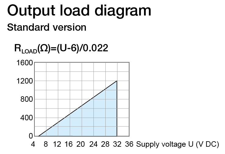 | ||||||||||||||
| Output signal (mA) | 4 to 20; 20 to 4 | |||||||||||||||
| Parametrization / Scaling | Configurable via NFC | |||||||||||||||
| Resolution | 0,4 | |||||||||||||||
| Measurment accuracy | 1 | |||||||||||||||
| Load | 750 Ω at 24 VDC | |||||||||||||||
| Connection type | 2-wire | |||||||||||||||
In-head transmitter - Time response | ||||||||||||||||
| Closing time / Update time (Inor) | ~150 - 300 | |||||||||||||||
| Heating period | The specified accuracy is reached after max. 4 minutes | |||||||||||||||
| Signal attenuation / Ajustable output filtering (Inor) | 0,15 to 75 adjustable via App | |||||||||||||||
| Measuring cycle | < 1 | |||||||||||||||
In-head transmitter - Sensor monitoring & sensor error | ||||||||||||||||
| Sensor break / Short circuit | Upscale (≥21.0 mA) or Downscale (≤3.6 mA) | |||||||||||||||
| Sensor failure effects (Inor) | according to NAMUR NE43 | |||||||||||||||
In-head transmitter - Accuracy and stability | ||||||||||||||||
| Typical accuracy | ||||||||||||||||
| RTD and Thermocouples | See table below | |||||||||||||||
| Resistance accuracy (digital) 1} | 0-1000 Ω: Max. ±40 mΩ or ±0,040 % of span 1000-10000 Ω: ±0,05 % or max. 1 Ω of span | |||||||||||||||
| Resistance accuracy (analog) 1} | ±0.06 % of span | |||||||||||||||
| Voltage accuracy (digital) 1} | ±5 µV or ±0.02 % of span | |||||||||||||||
| Voltage accuracy (analog) 1} | ±0.06 % of span | |||||||||||||||
| Temperature influence ±0.01 % of span per °C | 1} Total accuracy = Sum of digital and analog accuracy, calculated as an RMS (Root Mean Square) value | ||||||||||||||||
| Temperature influence | ||||||||||||||||
| RTD and Thermocouples | see table below | |||||||||||||||
| Resistance | ±0,01 % < 4000 Ω 2} < ±0,02 % of span per °C | |||||||||||||||
| Voltage | ±0,01 % of span per °C | |||||||||||||||
| Temperature influence ±0.01 % of span per °C | 2} 2000 Ω at 2-wire | ||||||||||||||||
| Cold junction compensation | ||||||||||||||||
| Temperature influence | ±0,01 °C per °C | |||||||||||||||
| Influence of the sensor cable | ||||||||||||||||
| RTD and resistance (2-wire) | Adjustable wire resistance compensation | |||||||||||||||
| RTD and resistance (3-wire) | Negligible, with equal wire resistance | |||||||||||||||
| RTD and resistance (4-wire) | Negligible | |||||||||||||||
| Thermocouples and Voltage | Negligible | |||||||||||||||
| Further data | ||||||||||||||||
| Supply voltage influence | Within specified limits <±0,005 % of span per V | |||||||||||||||
| Long-term drift | Max of ±0,02 °C or ±0,02 % of span per year | |||||||||||||||
In-head transmitter - Type | ||||||||||||||||
| Dimensions | See drawing | 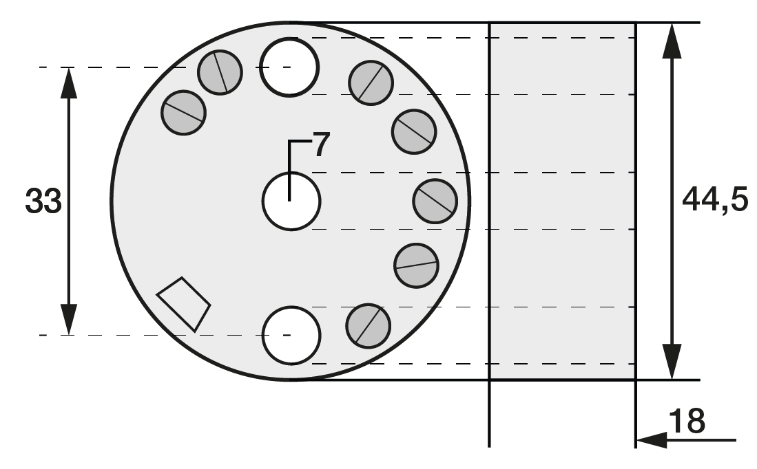 | ||||||||||||||
| Material | Flammability | PC/ABS + PA, V0/HB, RoHS compliant | |||||||||||||||
| Mounting | Rail according to DIN 50022 / EN 60715, 35mm / 1,38“ | |||||||||||||||
| Connection | Single wires, max. 1,5 mm², AWG 16 | |||||||||||||||
| Weight | 55 | All dimensions in mm | ||||||||||||||
In-head transmitter - General data | ||||||||||||||||
| Isolation | 1500 VAC, 1 min | |||||||||||||||
| Supply Voltage (VDC) | 8 to 36, polarity protected | |||||||||||||||
In-head transmitter - Ambient conditions | ||||||||||||||||
| Ambient Temperatur | Storage: -40 °C to +85 °C | -40 °F to +185 °F Operating: -40 °C to +85 °C | -40 °F to +185 °F | |||||||||||||||
| Humidity | 0 to 98 (non-condensing) | |||||||||||||||
| Protection | Housing IP20 | Anschlussklemmen IP20 | |||||||||||||||
| Vibration | according to IEC 60068-2-6, Test Fc, 10bis2000 Hz, 10 g | |||||||||||||||
| Shock | according to IEC-60068-2-27, test Ea | |||||||||||||||
| Environmental influences | according to IEC 60068-2-31:2008, Test Ec | |||||||||||||||
In-head transmitter - EMC | ||||||||||||||||
| Standard | Directive: 2014/30/EU | Harmonized standards: EN 61326-1, EN 61326-2-3 | NAMUR NE 21 | |||||||||||||||
| Immunity performance | EN61326-1 and -2-3: Criteria A | NE 21: <0,5% of span | |||||||||||||||
In-head transmitter - Factory configuration (if not ordered otherwise) | ||||||||||||||||
| Input | Pt100, 3-wire, 0 °C to 100 °C | |||||||||||||||
| Output (mA) | 4 to 20 | |||||||||||||||
| Sensor control | Upscale (≥21.0 mA) | |||||||||||||||
In-head transmitter - Mounting | ||||||||||||||||
| You can mount the APAQ C130 head transmitter in DIN B (or larger) connection heads or on the rail. Mounting is easy because you can easily pull out the sensor cable or the insertion tube through the large center hole Ø 7 mm. The electrical connection is made according to the wiring diagram. We offer mounting material for the installation of the transmitter as accessories. Depending on your requirements, you will find kits for head mounting and top hat rail mounting. Important: To prevent measuring errors, the connecting screws for fastening the connecting cable must be tightened firmly. | ||||||||||||||||
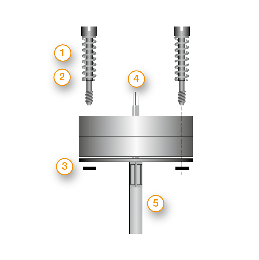 | (1) M4 screw (2) spring (3) Lock washer (4) Wires from measuring insert (5) MI cable | |||||||||||||||
 | ||||||||||||||||
| Mounting on the rail (1) Place the transmitter on the mounting clip. (2) Press the transmitter until it snaps firmly onto the clip (3) Now you can clip one end of the mounting clip onto the rail at an angle. (4) Then please clip the other end of the clip onto the rail as well. (5) You can detach the transmitter from the rail if you press the hook on the fastening clip with the screwdriver and lift the clip out of the rail at the same time. | ||||||||||||||||
In-head transmitter - Configuration | Parametrization | ||||||||||||||||
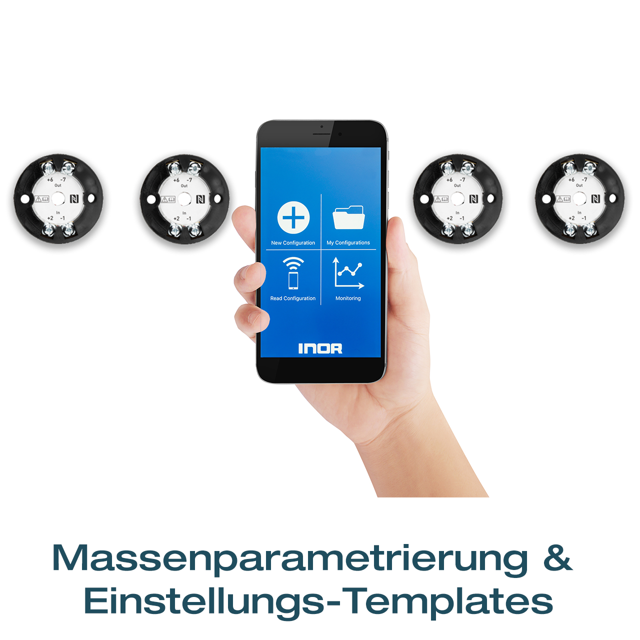 Before making a configuration of APAQ C130TC you need to do following: Make sure that you have a mobile device with NFC communication activated. Download the app INOR Connect to your mobile device. Required versions: iOS: iOS 13 or later and Iphone 7 or later Android: Android 4.4 or later | Configuration procedure: Launch the app by clicking on the App icon or holding your mobile device against the transmitter on the part of the device where NFC is located (only possible with Android). Click on “Read Configuration” and hold your mobile device against the transmitter as explained in the first section. In the app you can edit the following: Sensor type and number of wire circuits Measuring range Upscale or Downscale sensor control TAG-number Password settings In the configuration window you can enter and change the parameters. The selected configuration is transferred to the transmitter by clicking the "Send to transmitter" button. After the transfer is completed, the transmitter uses the new parameters. | |||||||||||||||
| Type: | In-head transmitter |
| Output: | 4-20 mA |
| Input: | Universal input |


